The use of spin currents in information transistors is predicted to offer non-volatility, faster data processing, higher integration densities and lower power consumption5,6,7, thanks to degrees of freedom emerging in quantum materials that exhibit unique spin-dependent properties, including topologically protected spin states5. At the same time, recent developments in antiferromagnetic spintronics have demonstrated that antiferromagnetic materials, such as NiO, provide a promising platform for spin injection and transport in the THz domain8 and spin-torque control9. Magnons, the collective excitations of the spin lattice in ferromagnets and antiferromagnets, which can be visualized semiclblockically as a wave of precessing magnetic moments10, are becoming a cornerstone of quantum technology11 through proposed spin-current-based device architectures. Of crucial importance are localized phenomena at the nanoscale and atomic scale, such as the scattering of spin waves at heterointerfaces and structural defects in materials, which can affect spin injection, spin-wave transmission, spin-torque switching and spin-to-charge conversion. As a result, the ability to achieve (sub-)nanometre-resolution magnon detection is considered one of the main challenges in the field of magnonics3,4.
Electrons as a probe for magnon excitations are commonly used through surface scattering of low-energy electrons in reflection high-resolution electron energy-loss spectroscopy (HREELS), using either spin-polarized or non-polarized electron sources10,12,13,14. Although HREELS can examine the energy–momentum dispersion of magnons with high energy resolution, it is limited to the study of surface excitations of ultrathin films over large length scales owing to limitations in the scattering cross-sections, spatial resolution and penetration depth intrinsic to the technique. Similarly, other experimental approaches widely used to study magnons at high energy and momentum resolutions, such as inelastic neutron scattering15, time-resolved Kerr microscopy16 or Brillouin light scattering17, are also fundamentally limited to spatial resolutions of hundreds of nanometres and often to large sample volumes. Consequently, magnon information from nanometre-sized features, such as defects and buried interfaces, is not accessible. New approaches in vector magnetometry using nitrogen-vacancy (NV−) centres sensing have recently shown great promise in mapping surface magnetic textures and detecting magnons at the nanometre-scale with high sensitivity18,19, although the fabrication of NV−-point-defect sensors remains challenging.
Since its first demonstration20,21, meV-level (vibrational) electron energy loss spectroscopy (EELS) in a scanning transmission electron microscope has been developing at a swift pace. Several key experimental milestones have been achieved: the detection of atomic-level contrast in vibrational signals22, the spectral signature of individual impurity atoms23, spatially resolved measurements on point and line defects in crystalline materials24,25, as well as momentum-resolved measurements using nanoscale beams26,27. With energy losses owing to magnon excitations occupying the same spectral window as phonons, ranging from a few to a few hundred meV in solid-state materials10,12,13,14, the promise of detecting magnons in an electron microscope is exciting from both fundamental research and applications points of view.
Recent theoretical studies on inelastic magnon scattering in an electron microscope confirmed the detectability of magnons as diffuse inelastic scattering and demonstrated the tantalizing prospect of obtaining atomically localized magnon information28,29,30. This exploratory work also highlighted experimental challenges such as the separation of phonon from magnon diffuse scattering, as the latter is predicted to be several orders of magnitude weaker than the former and yet occupy a similar energy-loss span. Here we tackle the challenges of detecting magnons at the nanoscale using high-resolution EELS in the scanning transmission electron microscope and we present the first direct detection of magnons with STEM-EELS. Furthermore, we demonstrate that, at the interface between a NiO thin film and a non-magnetic substrate, the magnon signal is exclusively confined within the film, confirming that magnons can be mapped with nanometre spatial resolution. We show that, although challenging, the detection of the inherently weak magnon signal is possible, thanks in part to the dynamic range of hybrid-pixel electron detectors31,32. The experiments are supported by state-of-the-art numerical simulations of electron scattering33, underpinned by atomistic spin dynamics (ASD) simulations34.
The primary challenge in achieving magnon EELS is that the energy ranges of phonon and magnon losses overlap, with the weaker magnon signal likely to be overshadowed by the inherently stronger lattice vibration modes. However, these types of loss follow different dispersion relations35 and, thus, should be differentiable in momentum-resolved experiments, given a suitable choice of material whose magnon and phonon branches are sufficiently separated in momentum and energy. For this purpose, we have selected NiO as a model system; as well as being of interest for spin-transfer-based devices36, its dispersion relations of phonon and magnon modes have been shown to meet our requirements of momentum and energy separation in the THz range37,38.
A schematic representation of the experimental geometry used for the momentum-resolved experiments is presented in Fig. 1a. The instrument’s electron optics are adjusted to a low convergence angle to form a diffraction-limited nanometre-sized electron probe, while achieving sufficient momentum resolution (Methods). The electron probe is kept stationary on a region of interest of the NiO crystal, across which the zone-axis orientation is perfectly maintained, estimated to extend no further than a few nanometres from the nominal probe position. The stability of the microscope sample stage, with typical drift measured of less than 0.5 nm per hour, enables hours-long acquisitions on a nanometre-sized area of the NiO crystal (Methods), a timescale still far shorter than necessary for magnon spectroscopy experiments using, for example, inelastic neutron scattering, for which days of integration from bulk samples can be required. A narrow rectangular (slot) collection aperture for EELS is used for the angle-resolved measurements39. The slot aperture is aligned to select a row of systematic Bragg reflections (Fig. 1b) and to produce two-dimensional intensity maps of energy loss (or frequency) ω versus momentum transfer q.
a, Schematic representation of the geometry of ω–q vibrational EELS measurements using a rectangular slot collection aperture. b, Experimental diffraction pattern along the NiO ([bar{1}10]) zone axis at a 2.25 mrad convergence angle, with the monochromating slit inserted, showing the orientation of the slot EELS collection aperture along the 220 row of systematic Bragg reflections in diffraction space. Scale bar, 2.5 Å−1, 20 mrad.
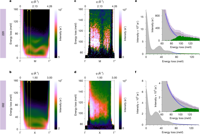
Figure 2 shows examples of such measurements acquired along the 220 and 002 rows of systematic Bragg reflections in NiO (corresponding to the Γ → M and Γ → X q paths, respectively). Figure 2a,b shows the as-acquired intensity maps of energy versus momentum transfer (ω–q maps). The ω–q maps show two intense bands dispersing around 30 and 50 meV, which correspond to the NiO longitudinal-acoustic (LA) and longitudinal-optical (LO) phonon branches, respectively, in agreement with previous experimental37 and theoretical work38,40. These are labelled on Extended Data Fig. 2, in which gain LA phonon branches are also visible (higher energy-gain branches are outside the recorded energy window).

a,b, As-acquired ω–q maps along the 220 and 002 rows of reflections, respectively, showing the dispersion of the NiO LA and LO phonon branches. For clarity, the intensity of the maps (calibrated in electrons, e−) is shown on a logarithmic colour scale. c,d, Background-subtracted ω–q maps showing the dispersion of the magnon bands at about 100 meV. e,f, Integrated spectra at the momentum positions marked by arrows in panels a and b. Insets, background-subtracted spectra (green-shaded area), obtained by removing a first-order log-polynomial model (blue line) from the raw signal (grey-shaded area). Pink-shaded areas illustrate the error bars as confidence bands at a +/−5σ level (σ is the standard deviation, calculated by blockuming that the magnon scattering and noise populations are Poisson distributed; see Supplementary Note 3).
Because the intensity of magnon EELS is expected to be much lower than that of phonons28,30, and given that magnon modes in NiO occur at higher energy losses compared with phonons, scaling the data by the square of the energy loss (intensity × E2) provides a useful means to enhance the visibility of weaker features above the decaying zero-loss-peak tail in the meV range, while avoiding possible errors in background fitting; see Supplementary Note 1. The scaled but otherwise unprocessed ω–q maps, presented in Supplementary Fig. 1b,e, readily show further spectral bands above 80 meV along Γ → M and Γ → X, which are present but hard to discern in the non-scaled data.
Subtracting the background from the tail of the phonon signal using a first-order log-polynomial model offers a clear illustration of the dispersion of the two spectral bands above 80 meV, shown in Fig. 2c,d for the Γ → M and Γ → X directions (with signal-to-noise ratios (SNRs) of 22 and 59, respectively; see Supplementary Note 3 for details on SNR estimation). Supplementary Note 2 explores the robustness of different background models.
In Fig. 2c, two lobes of spectral intensity are visible on either side of the M point, with a maximum peak at 100 meV. The intensity of the lobes is asymmetric around the M point, with a stronger signal between Γ and M compared with the lobe between M and Γ′. The intensity tends to 0 towards each of the Brillouin zone vertices. The same asymmetry is also evident in the 002 data (Fig. 2d) but the separation between lobes is less pronounced along the shorter Γ → X distances owing to limited momentum resolution and spectral smearing caused by averaging. Supplementary Fig. 3 shows how better branch separation can be achieved with less averaging at the cost of higher noise and lower SNR, as discussed in Supplementary Note 3.
The presence of these bands in the non-scaled data is confirmed in Fig. 2e by the integrated intensity profiles of the ω–q map over a narrow momentum window (Δq = 0.22 Å−1, to avoid spectral broadening through momentum averaging) at q = 1.24 Å−1, the value at which the intensity is maximum along Γ → M, marked by the yellow arrows and dashed lines in Fig. 2a. This highlights the shape of the peak, with a rising edge from 80 meV reaching a maximum at about 100 meV, before a weaker feature extending up to 120 meV. Similarly, in the integrated intensity profile of the Γ → X q path in Fig. 2f, the band at 100 meV is observed at q = 0.97 Å−1 (over a Δq = 0.2 Å−1 window; Fig. 2d), comparatively further away from the Γ point than the band observed in the Γ → M direction. This signal is unambiguously above the experimental error, as illustrated in Fig. 2e,f by confidence bands (pink-shaded areas) at a 5σ confidence level (σ is the standard deviation, calculated by blockuming that the magnon scattering and noise populations are Poisson distributed; see Supplementary Note 3).
The observed spectral bands emerge in the same energy–momentum space in which magnon modes are expected for NiO. The magnon density of states is known to shift to higher energies with decreasing temperature41, so the acquisition temperature difference explains a roughly 20 meV blueshift between EELS (room temperature) and neutron experiments (10 K in ref. 37), a conclusion borne out by simulations discussed below. Furthermore, the asymmetry of detected bands along both q paths, including their appearance most prominently above background further away from Γ in the Γ → X direction than along the Γ → M direction, is consistent with neutron-scattering experiments37,41. Here the asymmetry is also probably the result, in part, of the lower intensity away from the direct beam.
Owing to the overlap of the elastic (or zero-loss peak (ZLP)), phonon and magnon signals along q, it is difficult to quantify the absolute intensity of the observed bands we attribute to magnons. Nevertheless, an estimate can be given by the integral of the signal within the Γ → M → Γ′ window (excluding Γ points); after background subtraction (Fig. 2c), the integrated magnon intensity is estimated as roughly 8.5 × 10⁴ e−. For comparison, the corresponding integrated phonon intensity (for all branches) over the same Δq is three orders of magnitude higher, about 2.0 × 10⁷ e−, whereas the total integrated intensity across the slot aperture, blockumed to be representative of the total beam intensity impinging on the sample, was 5.2 × 10⁹ e−, in agreement with the expected relative intensities of the magnon and total scattered EELS signals28. A similar intensity ***ysis holds for the Γ → X data.
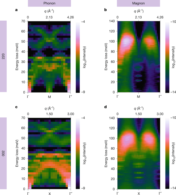
To support our experimental findings, we have performed first-principles calculations of momentum-resolved phonon and magnon EELS using parameters that reflect the experimental conditions, in particular the sample temperature, magnetic environment and the electron-optical parameters of the microscope (Methods). Figure 3 summarizes the results of the simulations for both experimental q paths. We observe phonon EELS bands reaching up to about 70 meV for both q paths, with a small gap around 40 meV (Fig. 3a,c). This matches the two dominant features observed in the experimental momentum-resolved phonon EELS datasets, albeit with a slightly higher energy-loss gap at 50 meV. Owing to the long acquisition times required to reveal the emergence of the magnon bands, and the chosen balance between momentum and spatial resolutions, some spectral smearing obscures the finer details of the experimental phonon dispersion. For completeness, a better-resolved ω–q map is presented in Extended Data Fig. 2 comparing very favourably with the calculated phonon dispersion in Fig. 3a (but in which the magnon signal is fainter as a result of shorter integration), and data acblockulation is discussed in Supplementary Note 3. The rich pattern observed in phonon simulations contrasts with magnon simulations, which show negligible fractional scattering intensities at energy losses below 60 meV, with two broad-yet-well-isolated peaks at energy losses between 80 and 120 meV (Fig. 3b,d).

a–d, Simulated momentum-resolved EELS (dispersion curves) of phonon (a,c) and magnon (b,d) excitations, along the Γ → M and Γ → X q paths of the Brillouin zone for NiO, respectively. Experimental parameters such as sample temperature, environmental magnetic field inside the microscope and electron-optical parameters are considered (Methods).
The theoretical calculations closely match the features emerging above the phonon EELS background observed in experiments (Fig. 2). The maximum simulated magnon EELS intensity appears around 100 meV at room temperature, as observed experimentally, whereas simulations of the magnon dispersion at 10 K (Extended Data Fig. 3) predict an energy-loss peak close to 120 meV, as expected from neutron experiments at this temperature. The measured asymmetry along the momentum axis, also present in neutron-scattering data, is well reproduced, showing a considerably higher intensity for the magnon EELS peak closer to the Γ point in the centre of the diffraction plane when compared with the peak near the 220 or 002 Γ′ points, respectively. This is intrinsic to the magnon EELS scattering strength, although, as discussed above, it is exacerbated experimentally owing to the lower intensity away from the direct STEM-EELS beam. Similarly, along the momentum direction, the calculated magnon intensity maximum is comparatively closer to the X point than to the M point, as in the experiments. Furthermore, the intensity peak shape in the energy-loss direction matches the experimental observations, with an extended spectral tail towards 120 meV in the Γ → M calculations, compared with a slightly more rounded peak centred at 100 meV in the Γ → X case. Theoretical and experimental integrated spectra and dispersions are shown side by side in Extended Data Fig. 4 and a broadened version of the simulations to mimic the finite experimental resolution is shown in Supplementary Fig. 4. These illustrate the excellent match and confirm the interpretation of the experimental intensities around 100 meV as being the spectral signature of scattering arising from magnon excitations in the nanometre-sized NiO crystal.
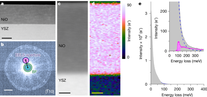
A key advantage of STEM-EELS is its unique ability to examine spectral signals at high spatial resolution. Spatially resolved measurements across a 30-nm-thick film of NiO grown on top of an yttrium-stabilized zirconia (YSZ) substrate demonstrate the potential of this technique for mapping magnons at the nanometre scale. Figure 4 shows a dark-field EELS experiment22, in which an angstrom-sized electron probe is rastered across the sample, the EELS signal being collected by a circular aperture displaced off the optical axis (Methods). This geometry was suggested in earlier work to be favourable for spatially resolved magnon detection28. An averaged spectrum shows a well-defined magnon peak at 100 meV (Fig. 4e), whereas—notably—the integrated map (Fig. 4d) shows that the signal is confined within the NiO film, disappearing completely within a sub-nanometre distance of the interface with the (non-magnetic) YSZ substrate and into the hole above the film surface. Spatially resolved spectral variations are explored in Supplementary Note 6.

a, High-angle annular-dark-field image of a 30-nm NiO thin film grown on a YSZ substrate. b, Experimental diffraction pattern along the NiO ([bar{1}10]) zone axis at a 31 mrad semi-convergence angle, with the monochromating slit inserted, showing the off-axis displacement of the round EELS collection aperture along the [002] direction (marked by the black arrow). c, Asymmetric (displaced) annular-dark-field image acquired during EELS measurements. d, Integrated intensity map of the magnon peak over the energy window indicated by a shaded area, after background subtraction, as illustrated in e with the signal integrated over the whole NiO film area (the background-subtracted version is presented, pink curve, inset). Scale bars, 15 nm (a); 7.7 Å−1, 60 mrad (b); 5 nm (c,d).
Inelastic magnon simulations for a thin slab of NiO are consistent with the experiments and predict a smaller intensity of the magnon signal at the edges of the slab compared with its centre, with a broader, more featureless post-peak tail (Supplementary Figs. 7 and 8). The thorough interpretation of signal differences near heterointerfaces would require the development of appropriate modelling frameworks and the observed drop in signal intensity observed near the interface with YSZ may have other causes (for example, beam propagation). Nevertheless, this experiment demonstrates unambiguously the nanometre-scale mapping of magnons in an electron microscope.

