Precision measurements of the magnetic properties of simple systems stand as a powerful tool for investigating fundamental physics, enabling some of the most precise tests of symmetry violations. For instance, the experiments described in ref. 11 used a 3He/129Xe comagnetometer to place tight constraints on CPT-invariance-violating and Lorentz-invariance-violating parameters for neutrons12. Incoherent studies of the magnetic properties of single electrons13 provide unparalleled tests of the Standard Model, while also setting constraints on the parameter space in which the dark photon could exist14. Meanwhile, direct measurements on 3He+ and 9Be+ ions have established the most precise absolute magnetometers so far15 and test multi-electron shielding factors16. Our experiments focus on antimatter-based magnetometry17 using cryogenic multi-Penning-trap systems. We have measured the proton (p) magnetic moment with a fractional accuracy of 300 ppt (ref. 18) and determined that of the antiproton ((bar{p})) with 1.5 ppb resolution8. These experiments are based on incoherent spin-projection measurements using the continuous Stern–Gerlach effect19,20, combined with decoherent measurements of the Larmor νL and the cyclotron νc frequencies in the magnetic field B0 = 1.945 T of our PT (ref. 21). The ratio of the measured frequencies gives the gyromagnetic g-factor g/2 = νL/νc. Decoherent Larmor resonance spectroscopy results in suppressed spin inversion and contributes to the broadening of the measured resonance lines, both of which diminish measurement resolution. Establishing coherent techniques to overcome these limitations is an exciting prospect and represents a key advancement towards establishing nuclear magnetic moment measurements at substantially improved resolution.
Here we demonstrate the coherent quantum transition spectroscopy of a single nuclear spin 1/2 particle—a single trapped antiproton. The measurements are carried out in the multi-Penning-trap system of the BASE collaboration17 at the Antiproton Decelerator (AD)/ELENA facility of CERN. By applying our unique two-particles/three-traps technique8, supported by our cooling trap (CT)22, we observe Rabi oscillations of a single (bar{p}) spin and achieve spin coherence times greater than 50 s. In line-shape scans, in which we vary an applied spin-flip radiofrequency νrf with respect to the Larmor frequency ({nu }_{{rm{L}}}=left(frac{{g}_{bar{p}}}{2}right)times {nu }_{{rm{c}}}), we obtain spin inversions greater than 70% and a full width at half maximum (FWHM) of the spin-transition resonance that is below 200 mHz. This is more than ten times narrower than in our previous antiproton magnetic moment measurements8. We show that the FWHM is, at present, limited by decoherence induced by cyclotron frequency measurement noise. This is a crucial step towards improved measurements of the p and (bar{p}) magnetic moments with a fractional accuracy less than 100 ppt and will allow for searches of time signatures of asymmetric antimatter/dark matter coupling23 at improved mblock resolution and increased data-taking rate, thanks to the higher signal-to-noise ratio and smaller FWHM of the coherent measurements.
The heart of our experiment is a superconducting solenoid magnet with a horizontal bore, operated at a magnetic field of B0,PT = 1.945 T. Inside the bore, the cryogenic multi-Penning-trap system, shown in Fig. 1, is mounted. Most important for this study are the AT, in which the continuous Stern–Gerlach effect is applied19, the homogeneous PT, in which precision frequency measurements take place, and a park trap (PKT). AT and PT centres are separated by 73.4 mm and PT and PKT centres are separated by 18.6 mm. The trap stack is placed inside a cylindrical hermetically sealed, pinched, cryo-pumped vacuum chamber, in which pressures less than 10−18 mbar and (anti)particle storage times of years are achieved24. The trap electrodes, designed as in ref. 25, are primarily made out of gold-plated copper. The central ring electrode of the AT is made of ferromagnetic CoFe, also gold-plated, which distorts the magnetic field in the centre of the trap to BAT(z) = B0,AT + B2,AT × (z − zAT,0)2, in which B0,AT = 1.231 T, B2,AT = 266(5) kT m−2 and zAT,0 is the trap centre (Fig. 1a). The magnetic field in the centre of the PT is BPT(z) = B0,PT + B1,PT × (z − zPT,0) + B2,PT × (z − zPT,0)2, with zPT,0 being the centre of the trap. Achieved with a local persistent magnet system, the coefficient B2,PT can be tuned in a range of about ±350 mT m−2. The gradient field B1,PT can be adjusted in a range between 10 mT m−1 and 24 mT m−1. Also part of the magnet system is a set of self-shielding solenoids26,27, with a shielding factor greater than 50. The trap electrodes are biased with ultrastable voltage sources. The applied voltages are selected such that, in the trap centres, homogeneous quadrupolar potentials Φ(z, ρ) = V0C2(z2 − ρ2/2) are formed25. Here V0 is the voltage applied to the central ring electrode, C2 is a geometry coefficient (Extended Data Table 1 and Methods) and z and ρ are cylindrical coordinates, for which z points along the magnetic field axis. A single particle in such crossed static fields oscillates at three independent frequencies28, at the modified cyclotron frequency ν+,PT ≈ 29.645 MHz, the axial frequency νz,PT ≈ 637 kHz and the magnetron frequency ν−,PT ≈ 7 kHz. An invariance theorem ({nu }_{{rm{c}}}^{2}={nu }_{+}^{2}+{nu }_{z}^{2}+{nu }_{-}^{2}) (ref. 28) relates the free cyclotron frequency νc = (qB0)/(2πm) to ν+, νz and ν−; here q and m are the charge and the mblock of the single trapped particle, respectively. Details on the eigenfrequencies and their measurements using non-destructive detection (see Fig. 1b) are described in Methods and summarized in Extended Data Tables 1 and 2.
a, Multi-Penning trap to demonstrate coherent spin quantum transitions with a single trapped antiproton. The trap stack consists of an antiproton reservoir trap, a park trap, a highly homogeneous and shielded precision trap, an blockysis trap to apply the continuous Stern–Gerlach effect and a trap to cool the antiproton’s modified cyclotron mode. The trap electrodes (golden) are spaced by sapphire rings (blue shading). b, Schematic of a single-particle detection system. The detector is represented by a parallel RLC circuit, with inductance L ≈ 2 mH, capacitance Cp ≈ 25 pF and Rp ≈ 150 MΩ. c, Magnetic bottle strength in the centre of the precision trap, as a function of current applied to the persistent local superconducting magnet. Error bars are smaller than the size of the data points. d, Non-destructive detection of spin transitions in the centre of the blockysis trap by measuring the axial frequency of the single trapped antiproton. Each frequency measurement takes around 120 s.
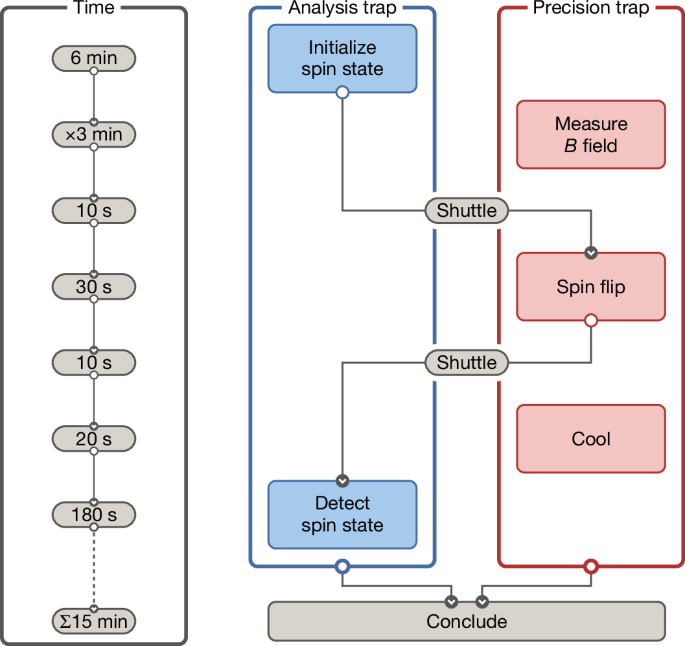
To implement the coherent spin transition spectroscopy, we use the two-particles/three-traps technique described in ref. 8. The measurement protocol is shown in Fig. 2. First, we initialize the spin state of a cold ‘Larmor’ particle in the AT. A second antiproton, the ‘cyclotron’ particle, is prepared in the PT for high-precision νc,PT measurements to determine the magnetic field of the trap29. After initialization, the Larmor particle is transported to the PT, at which a spin-flip drive is applied. The particle is then returned to the AT to determine whether a spin transition has occurred.

Illustration of the experiment sequence described in the text.
To begin, we first use the magnetic shimming system (Fig. 1a,c) and use measurements with the cyclotron particle to tune the magnetic coefficient B2,PT. In the case of finite B2,PT, interaction of the particle with the axial detector causes axial rms-amplitude fluctuations (propto ({k}_{{rm{B}}}{T}_{z}/)(m{omega }_{z}^{2})). These shift the Larmor frequency by ({Delta nu }_{{rm{L}}}=(1/{4{rm{pi }}}^{2})({nu }_{{rm{L}}}/{nu }_{z}^{2})({B}_{2}/{B}_{0})({k}_{{rm{B}}}{T}_{z}/m)) with the particle-to-detector correlation time of about 100 ms, causing motional spin decoherence. We thus tune B2,PT = 1.2(1.8) mT m−2, corresponding at the temperature Tz,PT = 8.5(3) K of the PT axial detector to spin coherence times longer than 1 h (ref. 28). Next, we apply the cooling protocol described in ref. 22 to the Larmor particle and cool it to a cyclotron energy E+/kB = T+ < 100 mK. Owing to the presence of the strong magnetic bottle B2,AT, a spin transition induces an axial frequency shift of Δνz,SF = 173(1) mHz (ref. 19). A sequence of axial frequency measurements νz,AT interleaved by spin transitions is shown in Fig. 1d.
To initialize the spin state of the Larmor particle, we apply a sequence of νz,AT measurements, each taking 120 s, followed by a 10 s injection of a magnetic spin-flip drive at νrf,AT = 51.651 MHz. At the background νz,AT scatter10 Ξback,AT ≈ 32(2) mHz achieved in this trap, we identify a measured νz,AT difference Δνz,SF > 140 mHz as a spin transition. This leads to spin-state initialization with a confidence of about 100%. Subsequently, we use the cyclotron particle in the PT to determine B0,PT in this trap. To that end, we measure νc,PT, using the technique described in ref. 29. A single cyclotron frequency measurement of approximately 180 s resolves νc with a fractional uncertainty of σ(νc,PT)/νc,PT = 1.42(7) ppb. This frequency defines the radiofrequency that is irradiated to later induce the coherent spin transitions in the PT νrf,SF,PT = (gp/2) × νc,PT, in which gp/2 = 2.7928473441 is used8. Next, we move the cyclotron particle to the PKT centre and the Larmor particle from the AT to the PT, by applying voltage ramps to the transport electrodes that interconnect the traps. Then a spin-flip drive at νrf,PT is irradiated for a time tSF,PT, transmitted by a coil mounted close to the PT (Fig. 1a). Afterwards, we move the Larmor particle back to the AT and the cyclotron particle to the PT and cool its magnetron mode. To identify whether the spin in the PT was flipped, we record a subsequent νz,AT/spin flip sequence to compare the spin state in which the particle was leaving the AT and once it returns from the PT. Here we identify a measured νz jump of Δνz > Δνz,SF/2 = 0.173/2 Hz as a detected spin transition21. The error rate of identifying the spin flips driven in the PT depends on the axial frequency scatter of the νz,AT sequences; the formalism to correctly estimate the error rate is described in refs. 30,31. The median axial frequency scatter of 32(2) mHz corresponds to an error rate less than 5%.
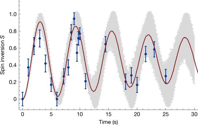
By applying this protocol and adjusting the radiofrequency interrogation time tSF,PT to drive spin transitions in the PT, we repeat the procedure 20 times for each value of tSF,PT, thereby obtaining the spin-flip probability P(tSF,PT), shown as the blue data points in Fig. 3. This corresponds to the first observation of Rabi oscillations with a single nuclear spin 1/2 antiparticle. The red line is a Monte Carlo fit (Methods and Extended Data Table 3) of
$$L({varOmega }_{0},Delta ,t)={int }_{-infty }^{infty }{P}_{{rm{SF,PT}}}({varOmega }_{0},Delta +sigma ,t)G(sigma ,;mu ,sigma ){rm{d}}sigma ,$$
in which the function
$${P}_{{rm{SF,PT}}}({varOmega }_{0},Delta ,t)=frac{{varOmega }_{0}^{2}}{{varOmega }_{0}^{2}+{Delta }^{2}}times {sin }^{2}({rm{pi }}sqrt{{varOmega }_{0}^{2}+{Delta }^{2}}times t),$$
is the spin-flip probability with Rabi frequency Ω0, detuning Δ = νrf,PT − νL and interrogation time t. The function G(µ, σ) is a Gaussian distribution, defined by the scatter σ ≈ 52 mHz, arising from the νc,PT measurement noise present during these experiments. This noise leads to an observed decay of spin inversion, to which an effective spin coherence time of τs,PT = 50.2(4.8) s can be blockigned. For further details on the blockysis, see Methods. This indicates that, in an optimized Rabi resonance scan, executed on the π-pulse, a FWHM ΔνFWHM ≈ 20 mHz or 250 ppt could be achieved. We note that magnetic noise imposed by the accelerator reduces the spin coherence time to 5.6(4) s (Extended Data Fig. 1).

Observation of coherent Rabi oscillations of the spin of a single trapped antiproton. The blue points represent the measured data and the red line depicts a Monte Carlo fit, which blockumes 52 mHz cyclotron frequency measurement decoherence as determined in the related measurements. In grey are the uncertainties of the Monte Carlo simulation. The effective coherence time is τs,PT = 50.2(4) s. Each point is an average of 20 spin flip attempts, uncertainty bars represent the standard deviations of the measured data distributions. Throughout the measurement campaign we have recorded several of these plots for different Rabi frequencies.
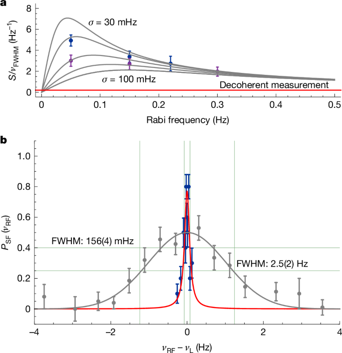
To optimize the spectral response of the coherent dynamics for measurements at optimum line-centre resolution, we first record Rabi oscillations at different drive amplitudes and determine the tSF,PT in the PT at which maximum inversion is achieved. At the determined optimum tSF,PT, we perform Larmor resonance scans, keeping tSF,PT constant while scanning the frequency νrf,PT of the spin-flip drive with respect to νL = (g/2) × νc,PT. Here νc,PT is obtained with the cyclotron particle in the PT, extracted from a sequence of six frequency measurements, taken before the application of the spin-flip drive. To resolve the resonance, we sample ten points per irradiated νrf,PT and scan each resonance with a minimum amount of eight discrete frequency offsets, which typically takes 60 h. The recorded cyclotron frequency sequence allows us to study ΔνFWHM and the inversion S as a function of νc,PT averages used to reconstruct νL at the time when the spin-flip drive is applied in the PT. Averaging several magnetic field measurements for the νL reconstruction decreases the cyclotron frequency scatter σc,PT to about 30 mHz, which narrows the width of the Larmor resonance while increasing the inversion. This is shown in Fig. 4a, in which we plot the ratio of inversion S ∈ [0, 1] over the measured ΔνFWHM as a function of the Rabi frequency Ω0/(2π) applied to sampled spin resonances. The purple data points are for one νc,PT measurement and the blue points are for four averages that are used to extrapolate νL. The grey lines represent the calculated scalings for different cyclotron frequency fluctuations between σ = 30 and 100 mHz. More than four νc,PT averages, due to a random walk in the field of the superconducting magnet, adds further fluctuation, broadening the Larmor resonance line again.

a, Signal S/ΔνFWHM for different Rabi frequencies and σc,PT. The grey lines are calculated results for σc,PT = 30, 40, 60, 80 and 100 mHz. b, Measured coherent νL resonance at the optimized parameters found in the experiment, blue scatters and best least-squares fit of a Voigt profile to the data (solid red line). The grey data points are from the previously measured antiproton g-factor resonance8. The coherent line has 1.54 times higher signal-to-noise ratio and a FWHM (green vertical lines) that is about 16 times narrower than the width in ref. 8. For both plots, the uncertainty bars represent the standard deviations of the measured data distributions.
By systematically scanning the interrogation times and Rabi frequencies, we obtain at Ω0/(2π) ≈ 50 mHz and a drive time of 16 s a signal inversion of 0.77(4) at ΔνFWHM = 156(4) mHz, as shown in Fig. 4b. The blue data points represent the measurement described here and the red line is a fit of a Voigt profile. Compared with the previous most precise measurement of the antiproton magnetic moment8 (grey data in Fig. 4b), this corresponds to an increase of the inversion by a factor of 1.54 at a 16-fold reduction of the FWHM of the resonance line. The line-centre determination of the dataset is at a level of 12 mHz or 150 ppt statistical uncertainty, ten times more accurate than in ref. 8. Note that this resonance was sampled during a data-taking period of only about 60 h, whereas the data ac***ulation in our previous measurement took place over a period of two months.
The statistical uncertainty in determining the line centre of such g-factor resonances scales proportionally to ΔνFWHM/S. Consequently, on the basis of our coherent spin spectroscopy data, we infer that, under present experimental conditions—relative to those reported in ref. 8—an approximately 25-fold improvement in the statistical precision of the g-factor line-centre determination is achievable. However, the two-particle method introduces systematic limitations on the interpretation of the measured line centre. Specifically, the transfer of particles between the AT and the PT induces magnetic field variations and voltage settling drifts. These effects undermine the critical blockumption that the magnetic field remains constant between the νc,PT measurements and the application of the Larmor drive—a requirement for the precise determination of the antiproton magnetic moment. Quantifying the complete systematic uncertainty budget within the limited three-month annual shutdown of the accelerator remains a substantial challenge. Because accelerator operation reduces the spin coherence time by nearly an order of magnitude, systematic shifts during on and off periods differ. Although using a single-particle double-trap technique21 could mitigate the present systematic uncertainties, this approach would substantially extend the required data acquisition time—beyond what is feasible during the short shutdown windows. To address these limitations, we have developed the transportable antiproton trap BASE-STEP32, enabling the relocation of antiprotons to dedicated, quiet laboratory environments at HHU Düsseldorf and CERN. These facilities will host precision experiments not exposed to accelerator-induced magnetic field fluctuations. By combining coherent spin quantum spectroscopy with phase-coherent cyclotron frequency measurements in such an environment, it will become feasible to suppress magnetic field noise by at least a factor of five. This would allow statistical resolutions of the g-factor line centre at the level of approximately 10 ppt. The application of these techniques to the proton would open the path towards one of the most stringent tests of CPT invariance in the baryon sector12.

